Download top and best high-quality free Dish Antenna PNG Transparent Images backgrounds available in various sizes. To view the full PNG size resolution click on any of the below image thumbnail.
License Info: Creative Commons 4.0 BY-NC
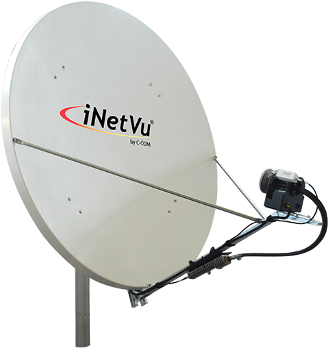
A parabolic antenna directs radio waves using a parabolic reflector, which is a curved surface having the cross-sectional form of a parabola. The most common design, which is shaped like a dish and is known as a dish antenna or parabolic dish, is the most frequent. A parabolic antenna’s primary benefit is its great directivity. It works in the same way as a searchlight or flashlight reflector in that it directs radio signals in a narrow beam or only receives radio waves from one direction. Parabolic antennas feature some of the greatest gains of any antenna type, allowing them to create the narrowest beamwidths. Because the parabolic reflector must be much larger than the wavelength of the radio waves used to achieve narrow beamwidths, parabolic antennas are used in the high frequency part of the radio spectrum, at UHF and microwave (SHF) frequencies, where the wavelengths are small enough to use conveniently-sized reflectors.
In applications such as microwave relay links that carry telephone and television signals between nearby cities, wireless WAN/LAN links for data communications, satellite communications, and spacecraft communication antennas, parabolic antennas are used as high-gain antennas for point-to-point communications. Radio telescopes also make use of them.
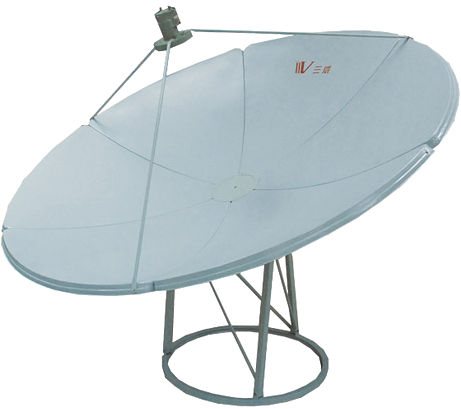
Another common application for parabolic antennas is radar antennas, which need the transmission of a narrow beam of radio waves to find things such as ships, airplanes, and guided missiles, as well as weather detection. With the introduction of home satellite television receivers, parabolic antennas have become a familiar sight in modern countries’ landscapes.
Heinrich Hertz, a German physicist, devised the parabolic antenna when he discovered radio waves in 1887. During his groundbreaking experiments, he employed cylindrical parabolic reflectors with spark-excited dipole antennas at their focal points for both transmitting and receiving.
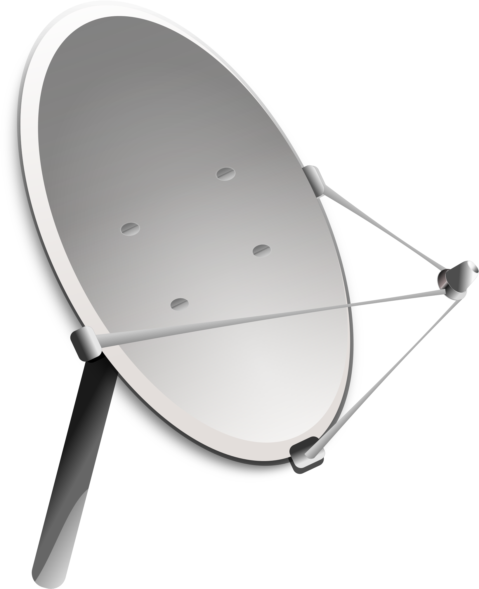
A point source of radio waves at the focal point in front of a paraboloidal reflector of conductive material is reflected into a collimated plane wave beam along the reflector’s axis, which is how a parabolic antenna works. An entering plane wave parallel to the axis, on the other hand, will be concentrated on a point at the focal point.
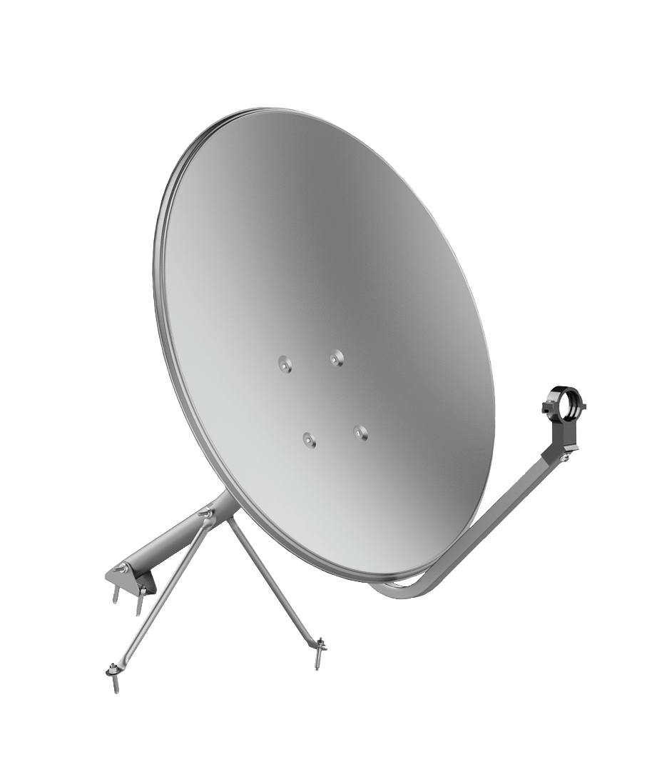
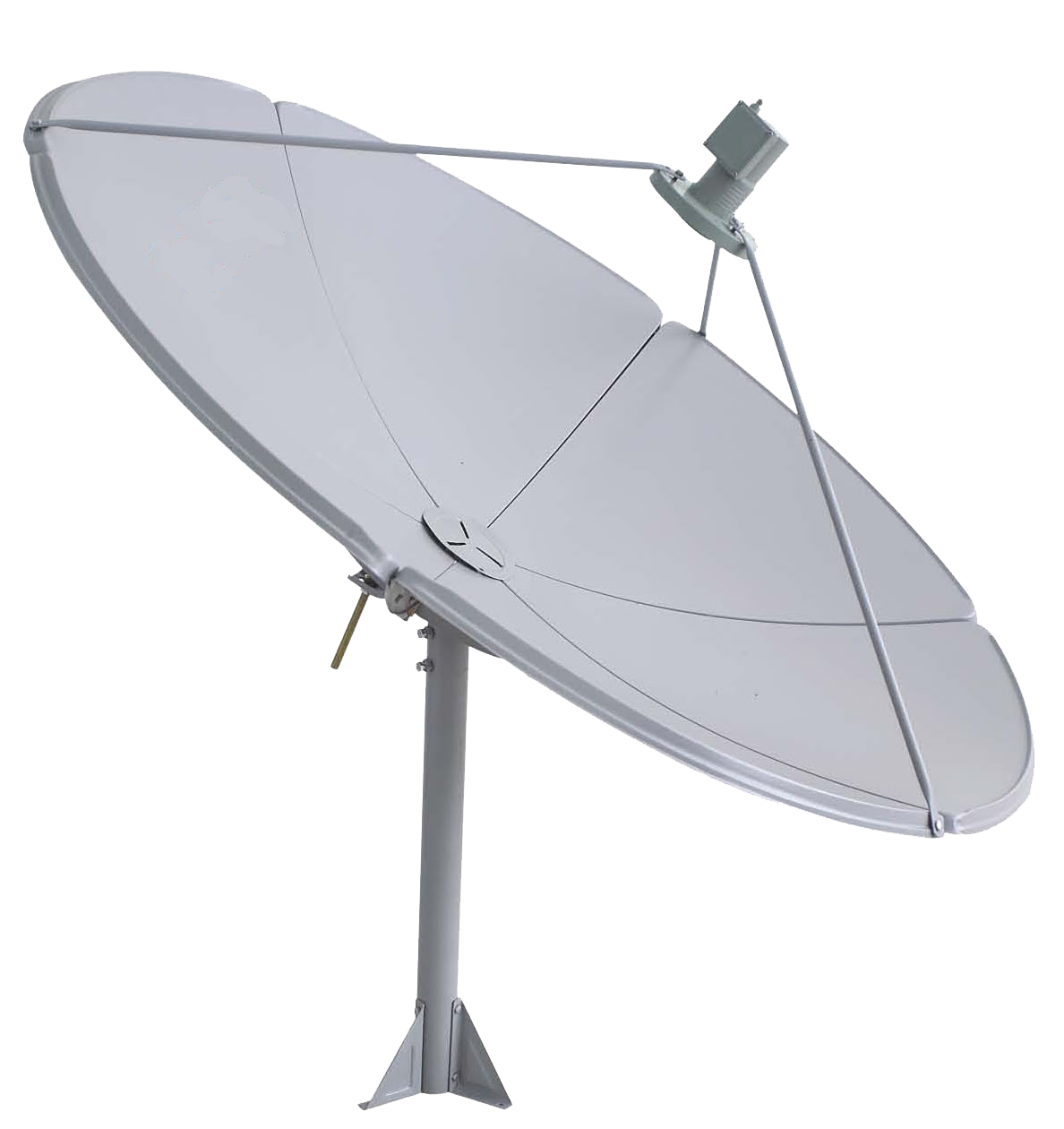
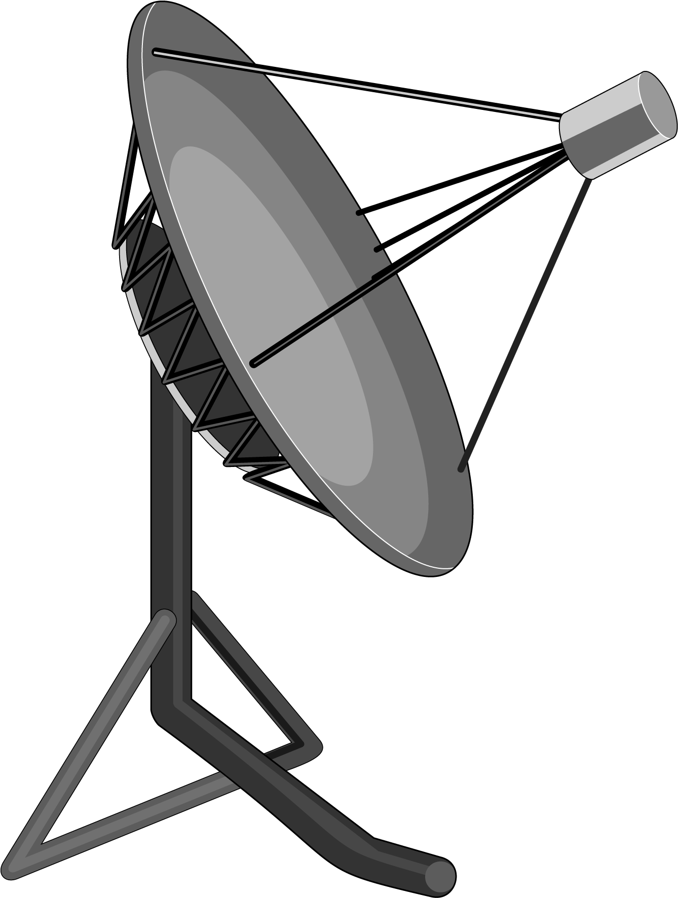
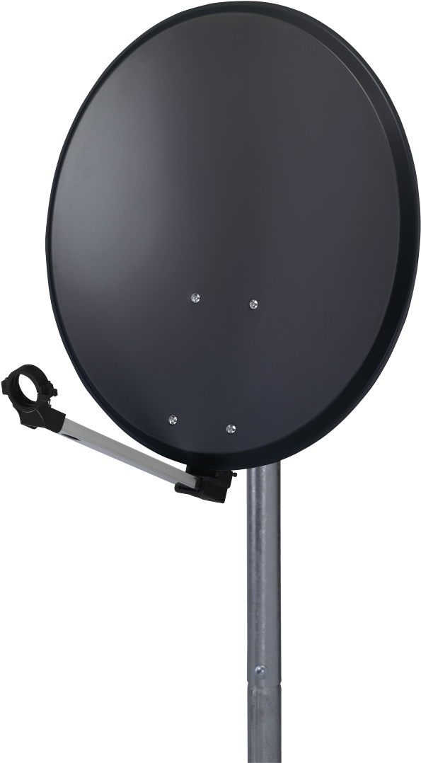
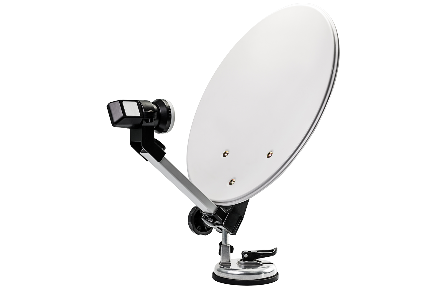
A conventional parabolic antenna consists of a metal parabolic reflector with a tiny feed antenna hanging in front of it at its focus and pointing back toward it. The reflector is a metal surface that has been shaped into a paraboloid of revolution and is generally terminated in a circular rim that defines the antenna’s diameter. The feed antenna of a transmitting antenna receives radio frequency current from a transmitter through a transmission line wire and transforms it to radio waves. The feed antenna emits radio waves back toward the dish, which reflect off the dish creating a parallel beam. In a receiving antenna, incoming radio waves bounce off the dish and are focussed to a point at the feed antenna, which transforms them to electric currents that flow to the radio receiver over a transmission line.
At a frequency of 2.5-2.7 GHz, a wire grid-type parabolic antenna is employed for the MMDS data connection. It’s supplied by a vertical dipole hidden behind the boom’s modest metal reflector. Vertically polarized microwaves are emitted.
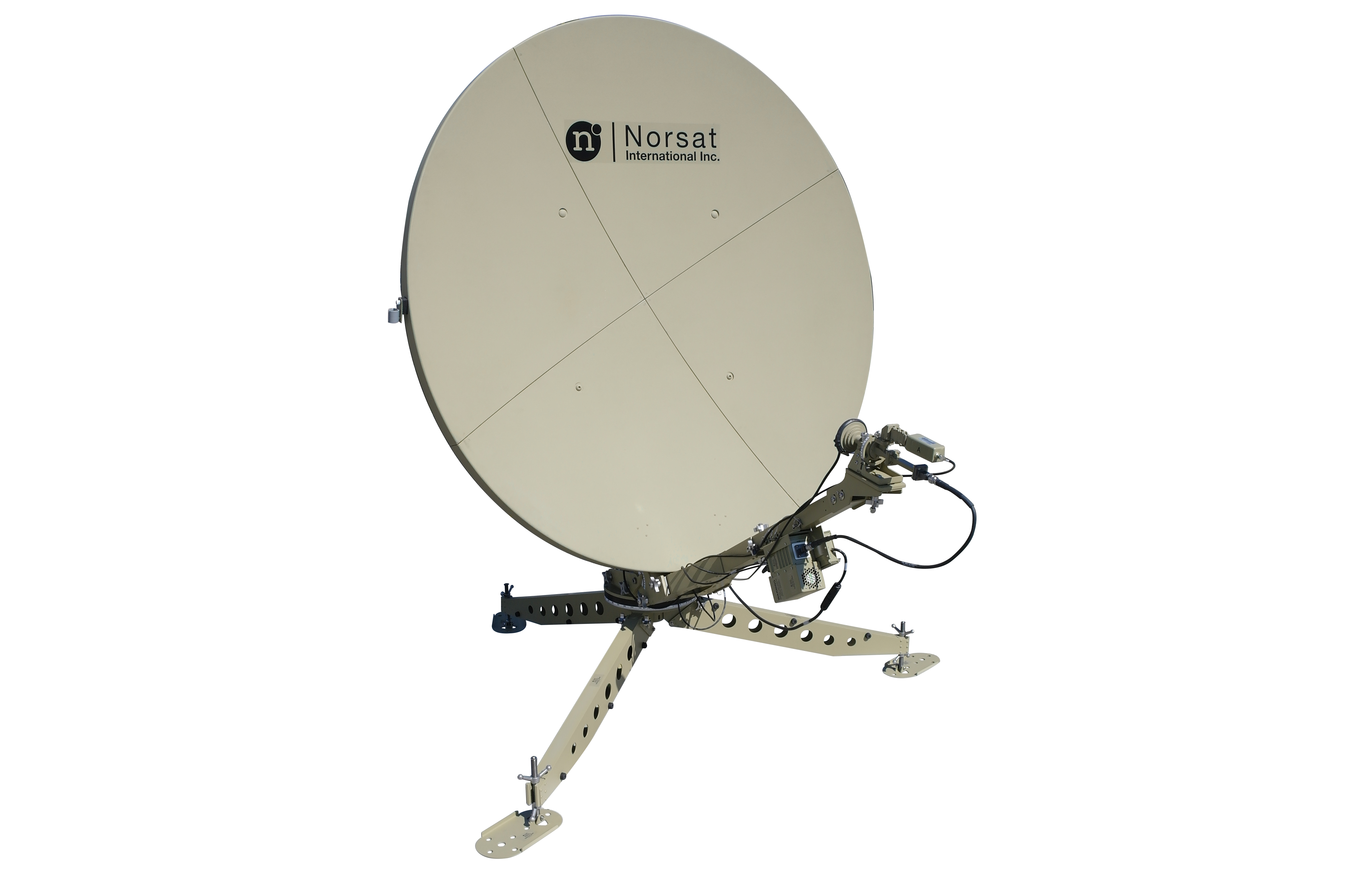
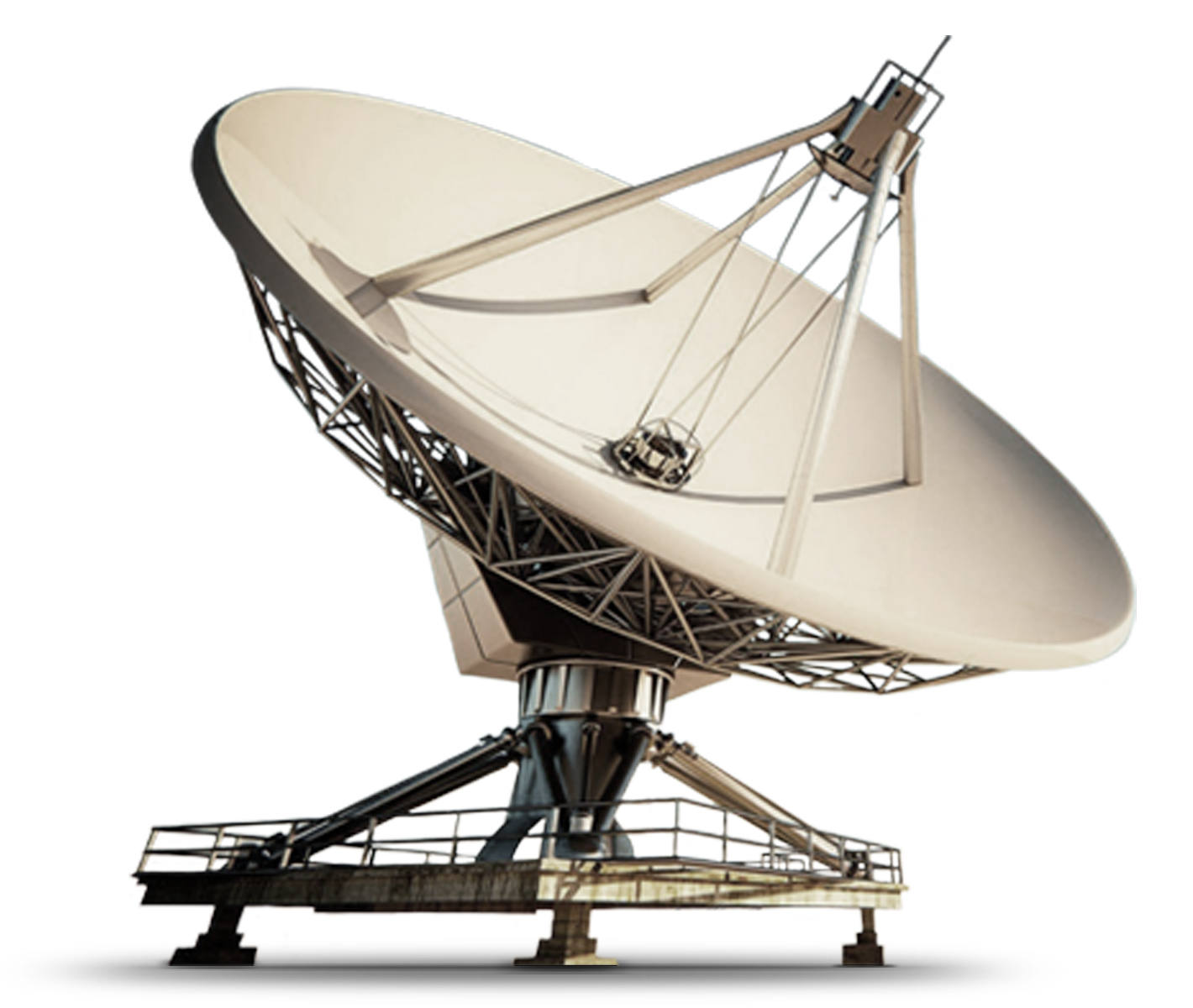
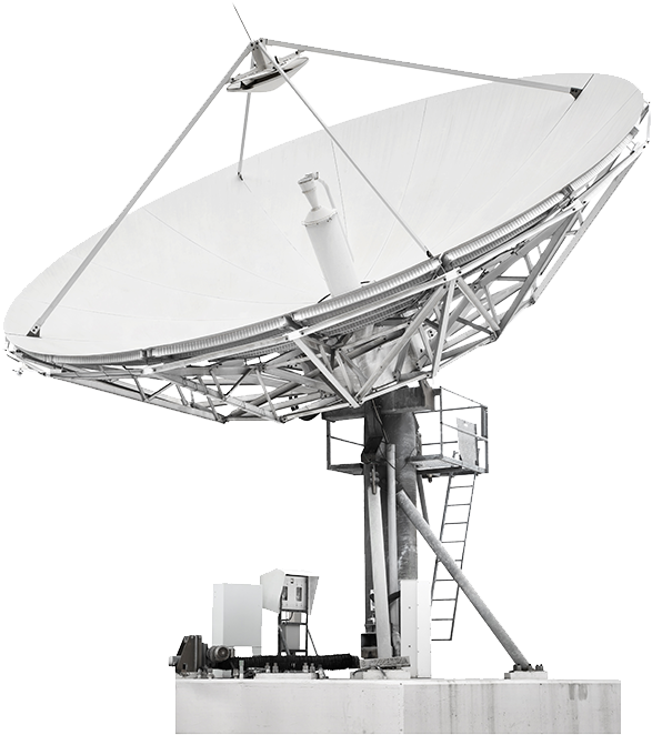
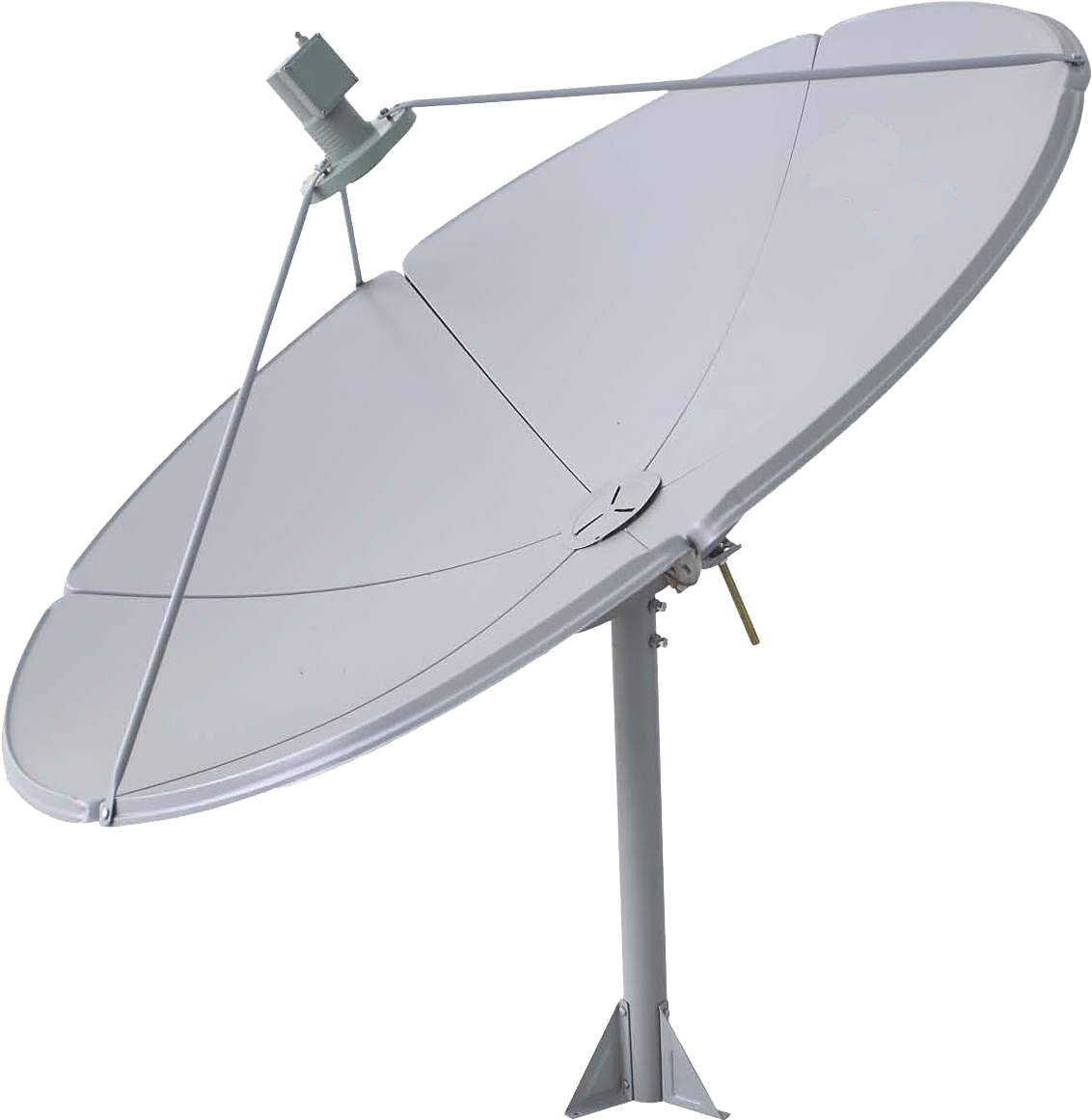
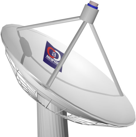
The reflector can be made of sheet metal, metal screen, or wire grill, and it can be shaped like a circular “dish” or any other form to generate multiple beam shapes. As long as the holes are less than one-tenth of a wavelength, a metal screen reflects radio waves as well as a solid metal surface, hence screen reflectors are frequently employed to minimize dish weight and wind loads. To obtain optimum gain, the shape of the dish must be correct to within a few hundredths of a wavelength, ensuring that waves from various regions of the antenna arrive to the focus in phase. To give the requisite rigidity, large dishes frequently require a supporting truss system behind them.
Download Dish Antenna PNG images transparent gallery
-

- Dish Antenna Dish Tv PNG Photo

Resolution: 462 × 512
Size: 7 KB
Image Format: .png
Download
-

- Dish Antenna PNG Cutout

Resolution: 512 × 512
Size: 9 KB
Image Format: .png
Download
-

- Dish Antenna PNG Images
Resolution: 560 × 980
Size: 29 KB
Image Format: .png
Download
-

- Dish Antenna Dish Tv PNG Cutout

Resolution: 558 × 534
Size: 50 KB
Image Format: .png
Download
-

- Dish Antenna PNG Photos
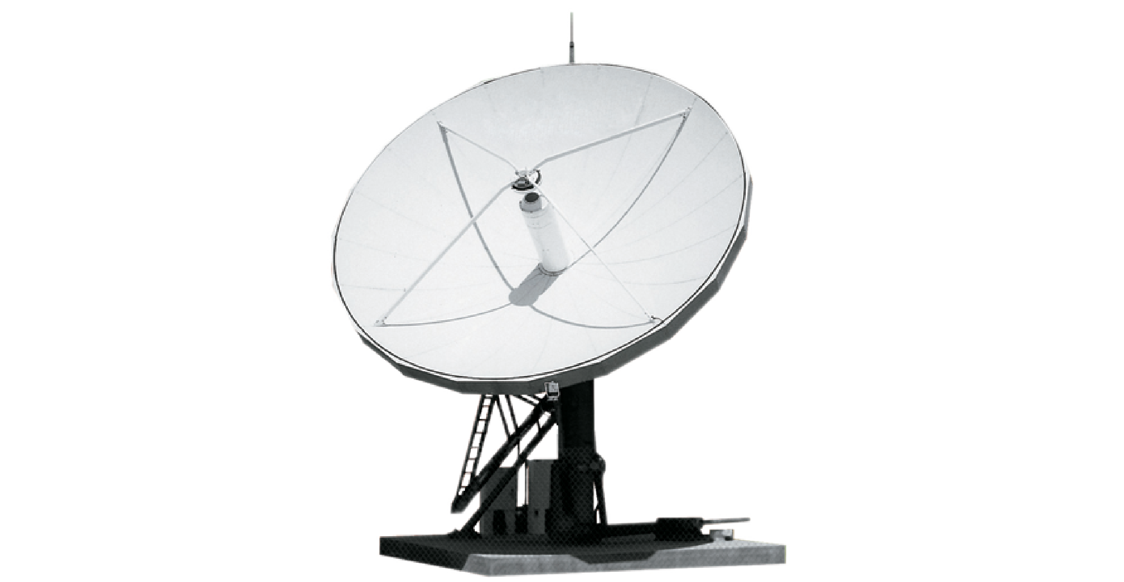
Resolution: 2282 × 1181
Size: 258 KB
Image Format: .png
Download
-

- Dish Antenna Dish Tv PNG Images

Resolution: 1011 × 1280
Size: 91 KB
Image Format: .png
Download
-

- Dish Antenna Transparent
Resolution: 560 × 720
Size: 59 KB
Image Format: .png
Download
-

- Dish Antenna PNG Clipart
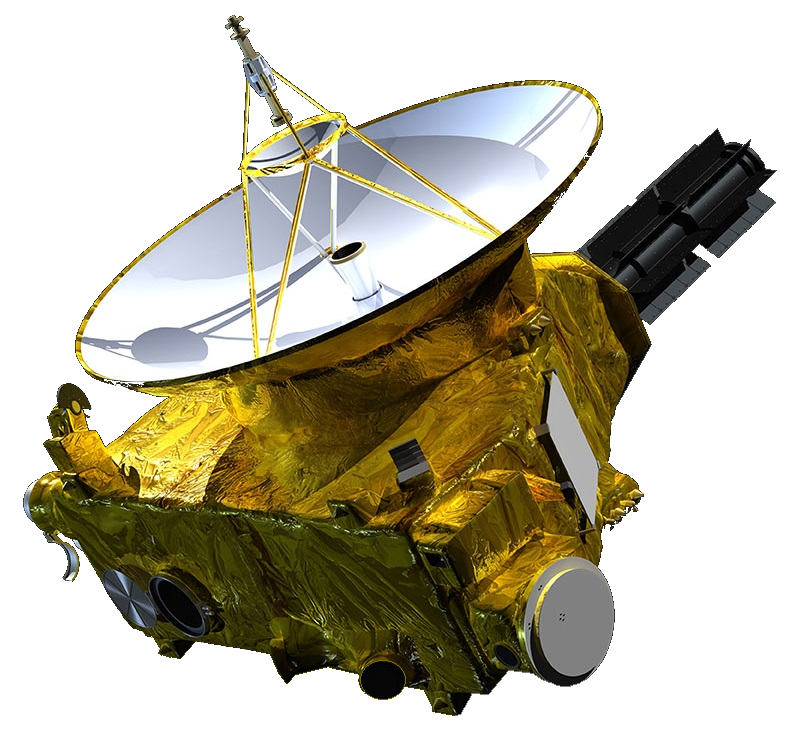
Resolution: 800 × 746
Size: 695 KB
Image Format: .png
Download
-

- Dish Antenna Dish Tv PNG Photos
Resolution: 914 × 1074
Size: 157 KB
Image Format: .png
Download
-

- Dish Antenna PNG Picture

Resolution: 1005 × 1280
Size: 458 KB
Image Format: .png
Download
-
- Dish Antenna PNG HD Image

Resolution: 512 × 512
Size: 27 KB
Image Format: .png
Download
-
- Dish Antenna PNG Image HD

Resolution: 512 × 512
Size: 15 KB
Image Format: .png
Download
-
- Dish Antenna No Background

Resolution: 512 × 512
Size: 117 KB
Image Format: .png
Download
-

- Dish Antenna PNG Images HD
Resolution: 521 × 339
Size: 80 KB
Image Format: .png
Download
-

- Dish Antenna Satellite
Resolution: 4828 × 3074
Size: 2989 KB
Image Format: .png
Download
-

- Dish Antenna Satellite PNG File

Resolution: 600 × 600
Size: 33 KB
Image Format: .png
Download
-

- Dish Antenna Satellite PNG Image
Resolution: 601 × 541
Size: 138 KB
Image Format: .png
Download
-

- Dish Antenna Satellite PNG Photo
Resolution: 1188 × 1260
Size: 350 KB
Image Format: .png
Download
-

- Dish Antenna Satellite PNG Cutout
Resolution: 1420 × 1200
Size: 1069 KB
Image Format: .png
Download
-

- Dish Antenna Satellite PNG Images
Resolution: 587 × 662
Size: 300 KB
Image Format: .png
Download
-

- Dish Antenna Satellite PNG Photos
Resolution: 1338 × 1773
Size: 126 KB
Image Format: .png
Download
-

- Dish Antenna Satellite Transparent
Resolution: 595 × 1078
Size: 436 KB
Image Format: .png
Download
-

- Dish Antenna Satellite PNG Clipart
Resolution: 1640 × 2016
Size: 434 KB
Image Format: .png
Download
-
- Dish Antenna Satellite PNG

Resolution: 512 × 512
Size: 7 KB
Image Format: .png
Download
-

- Dish Antenna Satellite PNG Pic
Resolution: 479 × 508
Size: 221 KB
Image Format: .png
Download
-

- Dish Antenna Dish Tv
Resolution: 1132 × 1161
Size: 366 KB
Image Format: .png
Download
-

- Dish Antenna Dish Tv PNG
Resolution: 1500 × 1000
Size: 392 KB
Image Format: .png
Download
-

- Dish Antenna
Resolution: 474 × 476
Size: 103 KB
Image Format: .png
Download
-

- Dish Antenna Dish Tv PNG Pic
Resolution: 461 × 409
Size: 114 KB
Image Format: .png
Download
-

- Dish Antenna PNG

Resolution: 521 × 700
Size: 28 KB
Image Format: .png
Download
-

- Dish Antenna PNG Pic

Resolution: 961 × 961
Size: 90 KB
Image Format: .png
Download
-

- Dish Antenna Dish Tv PNG File

Resolution: 980 × 968
Size: 47 KB
Image Format: .png
Download
-

- Dish Antenna Dish Tv PNG Image

Resolution: 980 × 980
Size: 32 KB
Image Format: .png
Download
-

- Dish Antenna PNG File

Resolution: 2396 × 2397
Size: 162 KB
Image Format: .png
Download
-

- Dish Antenna PNG Image

Resolution: 1920 × 1920
Size: 19 KB
Image Format: .png
Download
-
- Dish Antenna PNG Photo

Resolution: 1920 × 1920
Size: 26 KB
Image Format: .png
Download