Download top and best high-quality free Network PNG Transparent Images backgrounds available in various sizes. To view the full PNG size resolution click on any of the below image thumbnail.
License Info: Creative Commons 4.0 BY-NC
An electrical network is a collection of electrical components that are linked together. An electrical circuit is a network with a closed loop that provides a current return path. Signals are linearly superimposable in linear electrical networks, which are made up entirely of sources (voltage or current), linear lumped elements (resistors, capacitors, inductors), and linear distributed elements (transmission lines). They can be more easily examined utilizing strong frequency domain techniques like Laplace transforms to derive DC, AC, and transient responses.
A resistive circuit is one in which all of the components are resistors with perfect current and voltage sources. The analysis of resistive circuits is less difficult than that of capacitor and inductor circuits. The outcome is a DC circuit if the sources are constant (DC) sources. Graph measurements and geometrical features may be used to simulate the effective resistance and current distribution properties of arbitrary resistor networks.
An electronic circuit is a network that incorporates active electronic components. Because such networks are typically nonlinear, they need more sophisticated design and analysis methods.
An active network has at least one voltage or current source that can continuously deliver energy to the network. There is no active source in a passive network.
One or more electromotive force sources can be found in an active network. A battery or a generator are two practical examples of such sources. Active components can give power gain, inject power into the circuit, and regulate current flow within the circuit.
There are no sources of electromotive force in passive networks. They are made up of passive components such as resistors and capacitors.
If the signals in a network obey the principle of superposition, it is linear; otherwise, it is non-linear. There are some exceptions to the rule that passive networks are linear. If a big enough current is applied to an inductor with an iron core, it can be pushed into saturation. The inductor’s behavior is significantly non-linear in this area.
Because all of the resistance, capacitance, and inductance of discrete passive components (resistors, capacitors, and inductors) is presumed to be localized (“lumped”) at one location, they are referred to as lumped elements. The lumped-element model is the name given to this design philosophy, and the networks created using it are known as lumped-element circuits. This is the standard method of circuit design. Because there is a substantial percentage of a wavelength across the component dimensions at high enough frequencies or for long enough circuits (such as power transmission lines), the lumped assumption no longer holds. For such scenarios, a new design paradigm known as the distributed-element model is required. Distributed-element circuits are networks that follow this approach.
Download Network PNG images transparent gallery
-

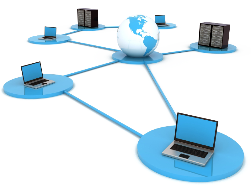
- Network PNG Photo

Resolution: 800 × 333
Size: 50 KB
Image Format: .png
Download
-

- Network PNG Cutout
Resolution: 800 × 600
Size: 245 KB
Image Format: .png
Download
-

- Network PNG Images

Resolution: 1049 × 609
Size: 530 KB
Image Format: .png
Download
-

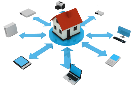
- Network PNG Photos

Resolution: 512 × 392
Size: 8 KB
Image Format: .png
Download
-

- Network People PNG

Resolution: 512 × 512
Size: 24 KB
Image Format: .png
Download
-

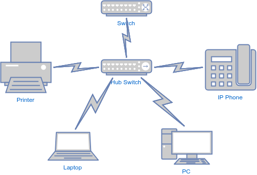
- Network Computer

Resolution: 512 × 482
Size: 11 KB
Image Format: .png
Download
-

- Network People PNG File

Resolution: 1200 × 1200
Size: 66 KB
Image Format: .png
Download
-

- Network Computer PNG

Resolution: 565 × 559
Size: 19 KB
Image Format: .png
Download
-
- Network Computer PNG Pic

Resolution: 512 × 512
Size: 12 KB
Image Format: .png
Download
-

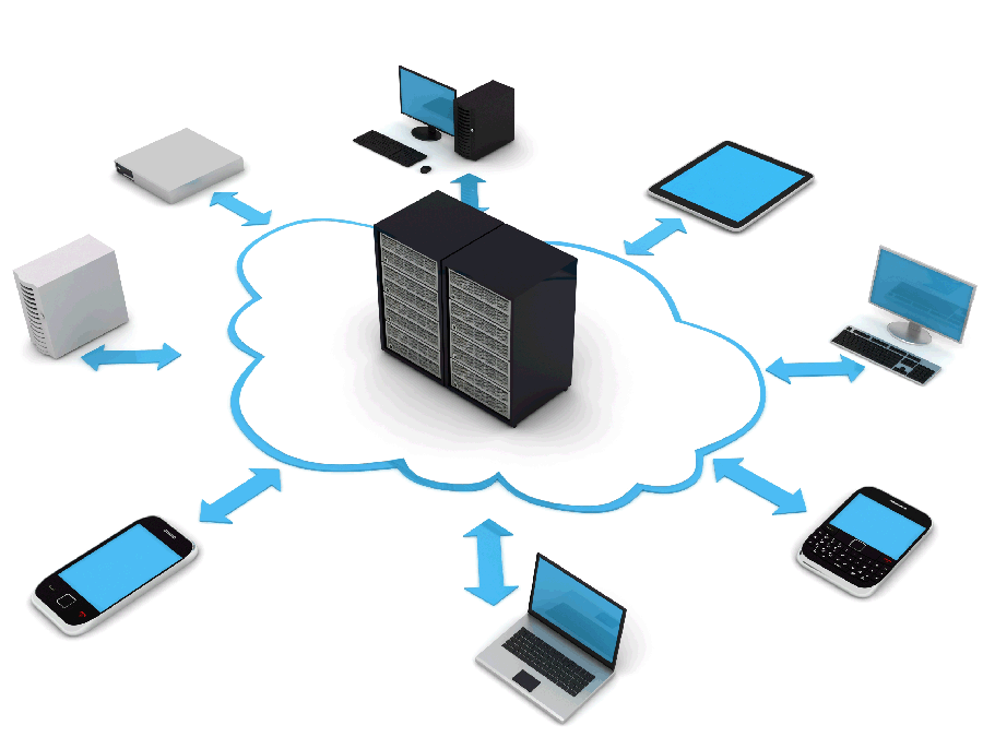
- Network Computer PNG File

Resolution: 935 × 928
Size: 169 KB
Image Format: .png
Download
-

- Network Computer PNG Image

Resolution: 1400 × 934
Size: 316 KB
Image Format: .png
Download
-

- Network Computer PNG Photo

Resolution: 980 × 982
Size: 51 KB
Image Format: .png
Download
-

- Network Transparent
Resolution: 900 × 675
Size: 160 KB
Image Format: .png
Download
-

- Network Computer PNG Cutout

Resolution: 1600 × 1200
Size: 662 KB
Image Format: .png
Download
-

- Network Computer PNG Images

Resolution: 600 × 478
Size: 9 KB
Image Format: .png
Download
-

- Network Computer PNG Photos
Resolution: 2000 × 1562
Size: 228 KB
Image Format: .png
Download
-

- Network Computer Transparent

Resolution: 1000 × 1286
Size: 63 KB
Image Format: .png
Download
-

- Network Computer PNG Clipart

Resolution: 630 × 720
Size: 35 KB
Image Format: .png
Download
-

- Network Computer PNG Picture

Resolution: 486 × 495
Size: 27 KB
Image Format: .png
Download
-

- Network Computer PNG HD Image
Resolution: 600 × 400
Size: 25 KB
Image Format: .png
Download
-

- Network Computer PNG Image HD
Resolution: 500 × 500
Size: 58 KB
Image Format: .png
Download
-

- Network Computer No Background
Resolution: 560 × 500
Size: 53 KB
Image Format: .png
Download
-
- Network Computer PNG Images HD
Resolution: 512 × 512
Size: 15 KB
Image Format: .png
Download
-

- Network Computer PNG Free Image

Resolution: 600 × 338
Size: 12 KB
Image Format: .png
Download
-

- Network Computer PNG Image File
Resolution: 1280 × 853
Size: 802 KB
Image Format: .png
Download
-
- Network PNG Picture

Resolution: 512 × 512
Size: 9 KB
Image Format: .png
Download
-

- Network Router
Resolution: 1280 × 640
Size: 55 KB
Image Format: .png
Download
-

- Network PNG HD Image

Resolution: 924 × 924
Size: 104 KB
Image Format: .png
Download
-

- Network PNG Image HD
Resolution: 511 × 347
Size: 25 KB
Image Format: .png
Download
-
- Network People

Resolution: 512 × 512
Size: 42 KB
Image Format: .png
Download
-

- Network People PNG Pic
Resolution: 460 × 300
Size: 75 KB
Image Format: .png
Download
-

- Network PNG Clipart

Resolution: 600 × 600
Size: 92 KB
Image Format: .png
Download
-

- Network People PNG Image

Resolution: 502 × 434
Size: 38 KB
Image Format: .png
Download
-

- Network No Background
Resolution: 1240 × 612
Size: 129 KB
Image Format: .png
Download
-

- Network

Resolution: 538 × 275
Size: 43 KB
Image Format: .png
Download
-

- Network PNG
Resolution: 800 × 462
Size: 94 KB
Image Format: .png
Download
-

- Network PNG Pic
Resolution: 3119 × 1615
Size: 72 KB
Image Format: .png
Download
-

- Network PNG File

Resolution: 512 × 457
Size: 81 KB
Image Format: .png
Download
-

- Network PNG Image

Resolution: 980 × 980
Size: 58 KB
Image Format: .png
Download