Download top and best high-quality free Speedometer PNG Transparent Images backgrounds available in various sizes. To view the full PNG size resolution click on any of the below image thumbnail.
License Info: Creative Commons 4.0 BY-NC
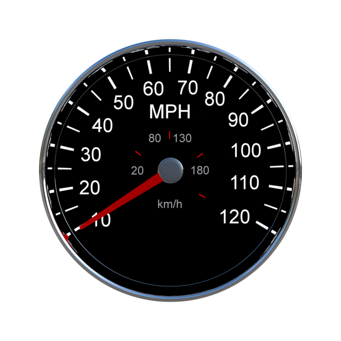
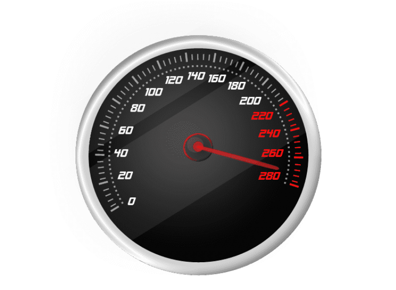
A speedometer, often known as a speed meter, is a device that monitors and shows a vehicle’s current speed. They first were available as choices in the early twentieth century, and then as standard equipment from around 1910 onwards. Other cars’ speedometers have different names and employ different methods of speed detection. This is a pit log for a boat. This is an airspeed indicator for an airplane.
An early sort of speedometer, which was generally mounted to locomotives, is claimed to Charles Babbage.
The electric speedometer, initially known as a velocimeter, was designed by Croatian Josip Belui in 1888.
Josip Belui (Giuseppe Bellussich) was the first to patent the speedometer in 1888. In 1889, he displayed his innovation at the Paris Exposition Universelle. His device featured a pointer and a magnet, and it worked with electricity. On October 7, 1902, German inventor Otto Schultze patented his version (which, like Belui’s, relied on eddy currents).
A revolving flexible wire connected to the output of the vehicle’s gearbox is used to power the speedometer. However, many motorbikes and early Volkswagen Beetles employ a cable driven from the front wheel.
A speedometer gear assembly rotates a speedometer wire, which then turns the speedometer mechanism itself, while the vehicle is in motion. On the analog speedometer instrument, a small permanent magnet attached to the speedometer wire interacts with a small metal cup (called a speedcup) attached to the shaft of the pointer. The shifting magnetic field produced by the magnet rotating near the cup causes eddy current in the cup, which produces another magnetic field. The magnet exerts a torque on the cup, “dragging” it, and therefore the speedometer pointer, in the direction of rotation, despite the fact that there is no mechanical connection between them.
A fine torsion spring keeps the pointer shaft at zero. The magnet’s rotational speed causes the torque on the cup to rise. As a result, increasing the car’s speed causes the cup and speedometer pointer to twist against the spring. The cup and pointer will spin until the eddy currents on the cup are balanced by the spring’s opposing torque, at which point they will stop. Because the torque on the cup is related to the car’s speed and the spring’s deflection is proportionate to the torque, the angle of the pointer is proportional to the speed, allowing for evenly spaced speed markings on the dial. The pointer will remain steady and pointing to the proper number on the speedometer’s dial at any given speed.
The return spring is calibrated such that a specified speed indication on the speedometer corresponds to a specific cable revolution speed. The ratios of the tailshaft gears that drive the flexible cable, the ultimate drive ratio in the differential, and the diameter of the driven tires must all be taken into account in this calibration.
One of the most significant drawbacks of the eddy current speedometer is that it cannot display vehicle speed when in reverse gear since the cup would revolve in the other direction, causing the needle to hit its mechanical stop pin at zero.
Download Speedometer PNG images transparent gallery
-

- Speedometer PNG Photos
Resolution: 512 × 512
Size: 92 KB
Image Format: .png
Download
-

- Speedometer Transparent
Resolution: 1413 × 1414
Size: 2020 KB
Image Format: .png
Download
-
- Speedometer PNG Clipart
Resolution: 512 × 512
Size: 17 KB
Image Format: .png
Download
-

- Speedometer PNG Picture

Resolution: 1000 × 1000
Size: 229 KB
Image Format: .png
Download
-

- Speedometer PNG HD Image
Resolution: 800 × 800
Size: 357 KB
Image Format: .png
Download
-

- Speedometer Car PNG Clipart
Resolution: 745 × 745
Size: 340 KB
Image Format: .png
Download
-
- Speedometer PNG Image HD
Resolution: 512 × 512
Size: 94 KB
Image Format: .png
Download
-

- Speedometer No Background
Resolution: 3840 × 2372
Size: 939 KB
Image Format: .png
Download
-
- Speedometer PNG Images HD

Resolution: 512 × 512
Size: 26 KB
Image Format: .png
Download
-

- Speedometer PNG Free Image
Resolution: 459 × 352
Size: 58 KB
Image Format: .png
Download
-
- Speedometer PNG Image File

Resolution: 512 × 512
Size: 18 KB
Image Format: .png
Download
-

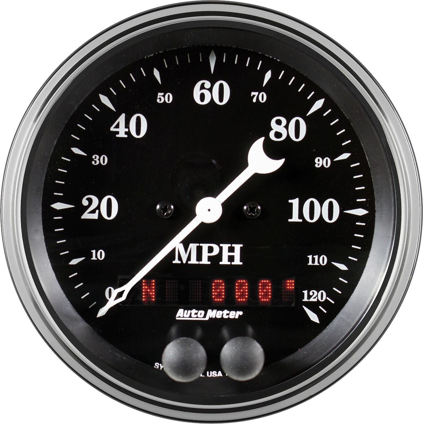
- Speedometer Car
Resolution: 700 × 700
Size: 166 KB
Image Format: .png
Download
-

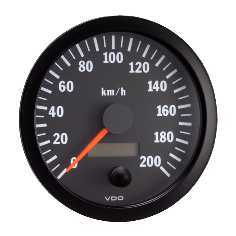
- Speedometer Car PNG Cutout
Resolution: 1200 × 1200
Size: 372 KB
Image Format: .png
Download
-

- Speedometer Car PNG Photos
Resolution: 1395 × 1395
Size: 832 KB
Image Format: .png
Download
-

- Speedometer Car Transparent
Resolution: 2688 × 2688
Size: 1645 KB
Image Format: .png
Download
-

- Speedometer Car PNG Picture

Resolution: 1280 × 1280
Size: 111 KB
Image Format: .png
Download
-

- Speedometer Car PNG HD Image
Resolution: 2000 × 2000
Size: 135 KB
Image Format: .png
Download
-

- Speedometer Car PNG Image HD
Resolution: 1463 × 1460
Size: 1459 KB
Image Format: .png
Download
-

- Speedometer Car No Background
Resolution: 2048 × 2048
Size: 385 KB
Image Format: .png
Download
-
- Speedometer Car PNG
Resolution: 512 × 512
Size: 231 KB
Image Format: .png
Download
-

- Speedometer Car PNG Pic
Resolution: 515 × 512
Size: 95 KB
Image Format: .png
Download
-

- Speedometer Car PNG File
Resolution: 2370 × 2370
Size: 3839 KB
Image Format: .png
Download
-

- Speedometer Car PNG Image
Resolution: 1875 × 1612
Size: 311 KB
Image Format: .png
Download
-

- Speedometer Car PNG Photo
Resolution: 600 × 600
Size: 75 KB
Image Format: .png
Download
-

- Speedometer
Resolution: 983 × 981
Size: 426 KB
Image Format: .png
Download
-

- Speedometer Car PNG Images
Resolution: 2066 × 1720
Size: 292 KB
Image Format: .png
Download
-

- Speedometer PNG
Resolution: 720 × 720
Size: 89 KB
Image Format: .png
Download
-

- Speedometer PNG Pic
Resolution: 4961 × 3442
Size: 523 KB
Image Format: .png
Download
-

- Speedometer PNG File
Resolution: 813 × 595
Size: 221 KB
Image Format: .png
Download
-

- Speedometer PNG Image
Resolution: 981 × 866
Size: 62 KB
Image Format: .png
Download
-
- Speedometer PNG Photo

Resolution: 512 × 512
Size: 28 KB
Image Format: .png
Download
-

- Speedometer PNG Cutout
Resolution: 980 × 852
Size: 29 KB
Image Format: .png
Download
-
- Speedometer PNG Images
Resolution: 720 × 720
Size: 49 KB
Image Format: .png
Download