Download top and best high-quality free Turbine PNG Transparent Images backgrounds available in various sizes. To view the full PNG size resolution click on any of the below image thumbnail.
License Info: Creative Commons 4.0 BY-NC
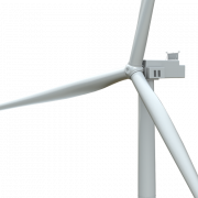
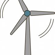
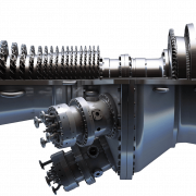
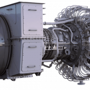
A turbine is a rotating mechanical device that collects energy from a fluid flow and turns it into usable work (from the Greek, tyrb, or Latin turbo, meaning vortex). When coupled with a generator, the work generated by a turbine may be utilized to generate electrical power. A turbine is a turbomachine having at least one moving component, the rotor assembly, which consists of a shaft or drum with blades attached. The blades rotate as a result of the moving fluid, imparting rotational energy to the rotor. Windmills and waterwheels are examples of early turbines.
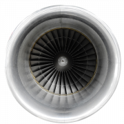
The working fluid is contained and controlled by a casing around the blades in gas, steam, and water turbines. Anglo-Irish engineer Sir Charles Parsons (1854–1931) is credited with the creation of the reaction turbine, whereas Swedish engineer Gustaf de Laval (1845–1913) is credited with the discovery of the impulse turbine. In modern steam turbines, both reaction and impulse are commonly used in the same unit, with the degree of response and impulse changing from the blade root to the blade periphery. In the first century AD, Hero of Alexandria proved the turbine concept in an aeolipile, and Vitruvius described them around 70 BC.
In 1822, French mining engineer Claude Burdin invented the term “turbine” from the Greek tyrb, which means “vortex” or “whirling,” in a letter titled “Des turbines hydrauliques ou machines rotatoires à great vitesse,” which he presented to the Académie royale des sciences in Paris. The first functional water turbine was developed by Benoit Fourneyron, a former student of Claude Burdin.
Potential energy (pressure head) and kinetic energy are both presents in a working fluid (the velocity head). It’s possible that the fluid is compressible or incompressible. Turbines capture this energy using a number of physical principles:
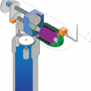
The direction of flow of a high velocity fluid or gas jet is changed using impulse turbines. The resultant impulse spins the turbine and reduces the kinetic energy of the fluid flow. The fluid or gas does not change the pressure in the turbine blades (the moving blades), as it does in a steam or gas turbine; instead, all of the pressure decreases occur in the stationary blades (the nozzles). By accelerating the fluid using a nozzle before it reaches the turbine, the fluid’s pressure head is converted to a velocity head. This technique is used only by Pelton wheels and de Laval turbines. Because the fluid jet is produced by the nozzle before reaching the rotor blades, impulse turbines do not require a pressure casement around the rotor. The energy transmission for impulse turbines is described by Newton’s second law. When the flow is low, and the intake pressure is high, impulse turbines are the most efficient.
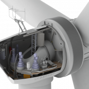
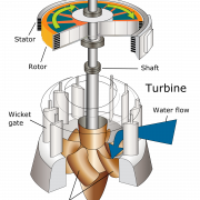
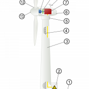
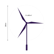
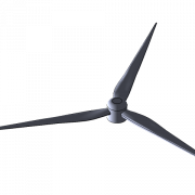
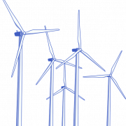
Reaction turbines generate torque by reacting to the pressure or mass of the gas or fluid. As the gas or fluid travels through the turbine rotor blades, the pressure of the gas or fluid varies. A pressure casement or the turbine must be entirely submerged in the fluid flow to confine the working fluid while it works on the turbine stage(s) (such as with wind turbines). The casing holds and guides the working fluid, as well as maintaining the suction imparted by the draft tube in water turbines. This is how Francis turbines and most steam turbines work. Multiple turbine stages are often utilized for compressible working fluids to efficiently harness the expanding gas. The energy transmission for reaction turbines is described by Newton’s third law. Reaction turbines are better suited to applications with greater flow rates or where the fluid head (upstream pressurization) is higher.
Download Turbine PNG images transparent gallery.
-

- Turbine

Resolution: 1360 × 442
Size: 410 KB
Image Format: .png
Download
-
- Power Turbine PNG High Quality Image
Resolution: 1379 × 1543
Size: 257 KB
Image Format: .png
Download
-
- Power Turbine PNG Image File
Resolution: 1074 × 1878
Size: 298 KB
Image Format: .png
Download
-
- Power Turbine PNG Images
Resolution: 858 × 1324
Size: 265 KB
Image Format: .png
Download
-
- Power Turbine PNG Photo
Resolution: 1000 × 1379
Size: 46 KB
Image Format: .png
Download
-
- Turbine Windmill Energy PNG
Resolution: 673 × 622
Size: 21 KB
Image Format: .png
Download
-
- Turbine Windmill Energy PNG Image

Resolution: 2243 × 2092
Size: 129 KB
Image Format: .png
Download
-
- Turbine Windmill
Resolution: 4015 × 3477
Size: 507 KB
Image Format: .png
Download
-
- Turbine Windmill PNG Download Image
Resolution: 1200 × 938
Size: 293 KB
Image Format: .png
Download
-
- Turbine PNG HD Image
Resolution: 1140 × 2375
Size: 52 KB
Image Format: .png
Download
-
- Turbine Windmill PNG High Quality Image
Resolution: 1024 × 576
Size: 95 KB
Image Format: .png
Download
-
- Turbine Windmill Energy Transparent

Resolution: 903 × 821
Size: 30 KB
Image Format: .png
Download
-
- Power Turbine PNG File Download Free

Resolution: 901 × 713
Size: 93 KB
Image Format: .png
Download
-
- Power Turbine PNG Image HD
Resolution: 4174 × 8685
Size: 245 KB
Image Format: .png
Download
-
- Power Turbine PNG Transparent HD Photo
Resolution: 640 × 480
Size: 12 KB
Image Format: .png
Download
-
- Power Turbine PNG
Resolution: 1012 × 1063
Size: 57 KB
Image Format: .png
Download
-
- Turbine Windmill PNG Images
Resolution: 640 × 1280
Size: 54 KB
Image Format: .png
Download
-
- Turbine Windmill PNG Image File
Resolution: 934 × 534
Size: 41 KB
Image Format: .png
Download
-
- Turbine Windmill PNG Photo
Resolution: 960 × 640
Size: 266 KB
Image Format: .png
Download
-
- Power Turbine PNG Image

Resolution: 1000 × 682
Size: 18 KB
Image Format: .png
Download
-
- Turbine PNG Pic

Resolution: 1916 × 2344
Size: 90 KB
Image Format: .png
Download
-
- Turbine Windmill PNG Image HD
Resolution: 640 × 1280
Size: 47 KB
Image Format: .png
Download
-
- Turbine Windmill PNG File Download Free
Resolution: 800 × 786
Size: 31 KB
Image Format: .png
Download
-
- Power Turbine Transparent
Resolution: 838 × 980
Size: 52 KB
Image Format: .png
Download
-
- Turbine Windmill PNG Transparent HD Photo
Resolution: 814 × 1280
Size: 101 KB
Image Format: .png
Download
-
- Turbine PNG Download Image
Resolution: 2000 × 2000
Size: 252 KB
Image Format: .png
Download
-
- Turbine PNG High Quality Image

Resolution: 981 × 930
Size: 32 KB
Image Format: .png
Download
-
- Turbine Windmill PNG

Resolution: 1920 × 1525
Size: 53 KB
Image Format: .png
Download
-
- Turbine PNG Images
Resolution: 770 × 500
Size: 114 KB
Image Format: .png
Download
-
- Power Turbine PNG Clipart

Resolution: 640 × 480
Size: 34 KB
Image Format: .png
Download
-
- Turbine Windmill PNG Image
Resolution: 960 × 640
Size: 321 KB
Image Format: .png
Download
-
- Power Turbine PNG Free Download

Resolution: 721 × 1024
Size: 17 KB
Image Format: .png
Download
-
- Turbine Windmill Transparent
Resolution: 934 × 534
Size: 13 KB
Image Format: .png
Download
-
- Power Turbine PNG Picture
Resolution: 750 × 639
Size: 80 KB
Image Format: .png
Download
-
- Turbine PNG Image File
Resolution: 2220 × 2880
Size: 734 KB
Image Format: .png
Download
-
- Turbine PNG Photo

Resolution: 1280 × 825
Size: 86 KB
Image Format: .png
Download
-
- Turbine Windmill PNG Clipart

Resolution: 934 × 534
Size: 47 KB
Image Format: .png
Download
-
- Turbine Windmill Energy PNG Clipart
Resolution: 786 × 980
Size: 21 KB
Image Format: .png
Download
-
- Turbine Windmill PNG Free Download

Resolution: 920 × 633
Size: 105 KB
Image Format: .png
Download
-
- Power Turbine PNG Free Image
Resolution: 1200 × 1714
Size: 188 KB
Image Format: .png
Download
-
- Turbine PNG Image HD

Resolution: 950 × 629
Size: 360 KB
Image Format: .png
Download
-
- Heavy Turbine
Resolution: 1920 × 818
Size: 1711 KB
Image Format: .png
Download
-
- Turbine Windmill Energy PNG Free Download
Resolution: 1378 × 1920
Size: 60 KB
Image Format: .png
Download
-
- Heavy Turbine PNG

Resolution: 901 × 816
Size: 96 KB
Image Format: .png
Download
-
- Heavy Turbine PNG Image
Resolution: 1280 × 960
Size: 865 KB
Image Format: .png
Download
-
- Turbine Windmill Energy PNG Picture
Resolution: 700 × 980
Size: 25 KB
Image Format: .png
Download
-
- Turbine Windmill Energy PNG Free Image
Resolution: 1600 × 1600
Size: 54 KB
Image Format: .png
Download
-
- Heavy Turbine Transparent
Resolution: 1920 × 914
Size: 1085 KB
Image Format: .png
Download
-
- Turbine Windmill PNG Picture
Resolution: 1440 × 1080
Size: 99 KB
Image Format: .png
Download
-
- Turbine Windmill Energy PNG File
Resolution: 640 × 480
Size: 22 KB
Image Format: .png
Download
-
- Turbine Windmill PNG Free Image

Resolution: 960 × 504
Size: 66 KB
Image Format: .png
Download
-
- Turbine PNG
Resolution: 960 × 630
Size: 47 KB
Image Format: .png
Download
-
- Heavy Turbine PNG Clipart
Resolution: 1280 × 558
Size: 338 KB
Image Format: .png
Download
-
- Power Turbine PNG File

Resolution: 1200 × 2442
Size: 57 KB
Image Format: .png
Download
-
- Turbine PNG Image

Resolution: 1280 × 640
Size: 300 KB
Image Format: .png
Download
-
- Turbine Transparent

Resolution: 1280 × 672
Size: 104 KB
Image Format: .png
Download
-
- Turbine PNG Clipart
Resolution: 649 × 720
Size: 52 KB
Image Format: .png
Download
-
- Turbine PNG Free Download

Resolution: 756 × 750
Size: 149 KB
Image Format: .png
Download
-
- Turbine Windmill PNG File

Resolution: 880 × 880
Size: 19 KB
Image Format: .png
Download
-
- Heavy Turbine PNG Free Download
Resolution: 640 × 480
Size: 157 KB
Image Format: .png
Download
-
- Power Turbine PNG HD Image

Resolution: 1024 × 1024
Size: 43 KB
Image Format: .png
Download
-
- Turbine Windmill PNG HD Image

Resolution: 1720 × 3000
Size: 41 KB
Image Format: .png
Download
-
- Turbine PNG Picture
Resolution: 1449 × 1636
Size: 219 KB
Image Format: .png
Download
-
- Power Turbine PNG Pic
Resolution: 800 × 800
Size: 101 KB
Image Format: .png
Download
-
- Turbine PNG Free Image

Resolution: 2000 × 2000
Size: 76 KB
Image Format: .png
Download
-
- Turbine PNG File

Resolution: 2431 × 2370
Size: 161 KB
Image Format: .png
Download
-
- Turbine Windmill PNG Pic
Resolution: 2209 × 2209
Size: 95 KB
Image Format: .png
Download
-
- Heavy Turbine PNG Picture
Resolution: 1600 × 1174
Size: 1723 KB
Image Format: .png
Download
-
- Turbine Windmill Energy
Resolution: 4564 × 9435
Size: 676 KB
Image Format: .png
Download
-
- Power Turbine

Resolution: 3009 × 1721
Size: 638 KB
Image Format: .png
Download
-
- Power Turbine PNG Download Image

Resolution: 2001 × 1153
Size: 293 KB
Image Format: .png
Download